Wednesday, December 24, 2008

Silvia - Arduino Pin Connections


I have just completed a table that is a summary of how all of the different hardware modules connect to the analog, digital, (+v), and ground pins on Arduino. These connections really follow directly from the software code that is used for this project. I thought that I'd just publish them in one place to help anyone contemplating the joining of Silvia and Arduino!

This table shows the module (hardware) to Arduino pin connections for two possible Silvia and Arduino configurations. The two configurations are designated by the interface method of input to Arduino, which in turn controls Silvia's actions.

If you want to use the Wii nunchuck as the interface for input to Arduino, then use the information provided in the column labeled: "ARDUINO PIN Wii Interface"

If you want to use a 6-button interface (of what ever design you like) for input to Arduino, then use the information in the column labeled: "ARDUINO PIN Button Interface"

Keep in mind that this table corresponds only to the specific hardware design that I used for the components in Silvia. My design differs from that of Tim Hirzel, this has to do with my use of the Opto 22 optoisolators to sense the status of the face panel switches, whereas Tim chose a low voltage re-wire of these switches. This then necessitated the use of two additional SSR's for control of the Silvia's pump and solenoid. If you want to go in Tim's direction, then the changes are self evident from looking at his SNV code.

One last note...

It was difficult to get this table to format for HTML, so if it is hard to read, just use ^Control + to make the text larger... good luck!!
Arduino Pin C
MODULEMODULE LEADARDUINO PIN
Wii
Interface
ARDUIO PIN
Button Interface
COMMENTS
Wii nunchuck


(+)3.3v


(-)GND


SDAANALOG 4
} I2C

SCLANALOG 5


Button Interface


UP
DIGITAL 36-button interface is used in place of the
Wii nunchuck.
Many hardware options are available

DOWN
DIGITAL 4

RIGHT
DIGITAL 5

LEFT
DIGITAL 6

C
DIGITAL 12

Z
DIGITAL 13


Real Time Clock


5v5v5v

GNDGNDGND

SQWDon't useDon't use

SDAANALOG 4ANALOG 4} I2C

SCLANALOG 5ANALOG 5


Temp Amplifier
AD595CQ


If LM34AH-ND is not used

5v5v5v

SIGANALOG 0ANALOG 0

GNDGNDGND


Temp Sensor
LM34AH-ND


If
AD595CQ
is not used

Vs+3.3v / 5v*3.3 / 5v** Adjust Calibration

VoutANALOG 0ANALOG 0

CASE (GND)GNDGND


Water Level Sensor
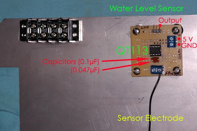
QT113


Lead from pin 15v5v

Lead from pin 2ANALOG 3ANALOG 3

Lead from pin 7Sensing ElectrodeSensing Electrode

Lead from pin 8GNDGND


PB4 Optoisolators1. (5v)5v5v

2. (GND)GNDGND

3. Top Center DIGITAL 11 DIGITAL 11

5. Lower DIGITAL 10 DIGITAL 10

7. MiddleDIGITAL 9DIGITAL 9

9. UpperDIGITAL 8DIGITAL 8


Sparkfun LCD


5v5v5v

GNDGNDGND

RXDIGITAL 3DIGITAL 2#define but don't use

TXDIGITAL 2DIGITAL 1


Heater Relay SSR


(+)DIGITAL 7DIGITAL 7

(-)GNDGND

Thursday, December 18, 2008

Progress Photos


Below are a few progress photos to give an idea of where the project is to date. All of the components that I will be installing internal to Silvia, have been installed. Those that will remain external, in an attached project box, have not yet been installed. In the next week of so, I plan to make my own project box, since I haven't been able to locate a box to purchase that is the size that I want to use.

The photos show some of the individual components prior to installation, the last photo illustrates the installation.


This image demonstrates the installation of the Solid State Relay (power supply to the boiler heating element) in the "usual" location, i.e., behind the lower front panel. The RED 5v supply wire is the PWM control from Arduino. The GREEN wire is connected to a common Arduino ground. The PURPLE wires out are the power supply to the heating element.


This photo shows the water tank, and the water level sensing probe. The sensing probe is made from a piece of copper de-soldering braid. The braid is soldered to a 22 AWG wire with a bullet connector at it's terminal end. The bullet connector allows for a "quick disconnect" in order to easily remove the water tank from Silvia when necessary. The braid is glued to the water tank using 3M's 5200 Marine Adhesive (really sticky stuff!).


Here the small printed circuit board that I made to organize the QT113 capacitance sensor that is used for water level detection, the Css reference capacitors, the 5v and ground supply, the input from the sensor electrode, and the output to Arduino. The board is attached to the stainless steel wall that separates the boiler compartment from the water tank / pump area inside Silvia. The PCB is screwed into nylon bushings that are glued to the stainless steel wall with the same 5200 Marine Adhesive.


This is how it all goes together as it will be installed


Now lets take a look at the IAC5 Optoisolators....

The four IAC5 optoisolators are installed on the PB4 data board which allows for really nice connectivity and organization. On the Control Side, each individual optoisolator is connected to one of Silvia's face panel switches (power, brew, steam, hot water). The Data Side outputs 5 vdc when each of the corresponding face panel switches are "off" and 0 vdc when the corresponding switch is "on". This way Arduino can "sense" the status of Silvia's face panel buttons.


This is how I installed the PB4 with the optoisolators. The PB4 is standing on an edge, you can see a white strip to the left of the numbers on the PB4; this strip is a piece of synthetic "asbestos" to act as a bit of a thermal insulator. There is another piece of this thermal insulator that I placed over the shaft of the steam valve too.


Here is a close up of the LM34AH temperature sensor. I made a small bracket out of a section of a wall of 1" copper tubing. It is shaped so that it's ID is just slightly bigger than the OD of the LM34AH. It holds the LM34 tightly against the boiler. You can see a bit of thermal conducting grease between the boiler and the temperature sensor.


Another view of the same thing. The LM34 is held down by one of the pressurestat screws (steam)


Ok... so this is the last photo for now... It shows how I managed to pack all of the components in the photos above into Silvia:


The legend to the numbers is as follows:

1. LM34AH IC Temperature Sensor
2. IA5c Optoisolators installed on the PB4 Data Board
3. Water Level Sensor - QT113 on the homemade pcb attached to the stainless steel dividing wall
4. Water Tank - water level prob is on the front outside surface of the tank but not visible in this view
5. Hard shell, split tube thermal insulator covering the tube connecting to the steam valve
6. Woven PPS Nomex thermal insulator for a few of the wires close to the boiler.

That's where I am to date... I just got the chrome goose neck that will attach the project box to Silvia. The project box will hold Arduino, the LCD, the Real Time Clock (RTC) module, and the input device (either the Wii nunchuck, or the button interface I am currently working on). Also, I didn't take a picture of it, but the 12vdc transformer that supplies Arduino has been "spliced" into Silvia's main power supply, and is located behind the stainless steel dividing wall, underneath the water tank, next to the ULKA pump.

More to follow, once the project is completed.........